English
 中文简体
中文简体 русский
 Español
 عربى
عربى
Material Selection for Butt Weld Fittings Choosing the right material is the first step in selecting...
A Guide to carbon steel Flanges and its Dimensions

Content
- 1 What Defines a Carbon Steel Flange Size?
- 2 Nominal Pipe Size: The Starting Point for Flange Identification
- 3 How to Measure Key Flange Dimensions Accurately
- 4 Carbon Steel Flange Dimension Reference Table
- 5 Pressure Class: Why It Changes the Physical Size of the Flange
- 6 Flange Face Types and Their Impact on Sizing
- 7 Reading Flange Markings and Heat Stamps
- 8 Common Mistakes When Identifying Carbon Steel Flange Sizes
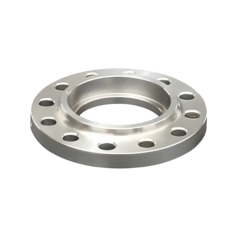
Identifying the correct flange size is one of the most critical tasks in piping system design, maintenance, and procurement. A mismatch in flange dimensions can lead to leaks, system failures, and costly downtime. Carbon steel flanges are among the most widely used in industrial piping due to their strength, affordability, and versatility — but they come in a broad range of sizes, pressure classes, and face types that must be correctly identified before any installation or replacement. This guide walks you through everything you need to know about how to tell flange size on carbon steel flanges, including the key dimensions to measure and the standards that govern them.
What Defines a Carbon Steel Flange Size?
A flange's "size" is not a single measurement — it is a combination of several dimensional parameters that together define whether two flanges are compatible and suitable for a given service. Carbon steel flanges manufactured to ASME B16.5 and ASME B16.47 standards are the most common in industrial piping, and their dimensions are precisely specified within those documents.
The primary dimensional identifiers for any carbon steel flange include the nominal pipe size (NPS), the pressure class rating, the bolt circle diameter, the number and diameter of bolt holes, the outer diameter of the flange, the flange thickness, and the bore diameter. Understanding each of these parameters and how they interact is essential for accurate flange identification in the field or during engineering design.
Nominal Pipe Size: The Starting Point for Flange Identification
Nominal pipe size (NPS) is the first and most fundamental dimension used to describe a carbon steel flange. It is important to understand that NPS is a standardized designation and does not directly correspond to any physical measurement on the flange itself. For pipe sizes 14 inches and above, the NPS does equal the outer diameter of the pipe in inches, but for sizes below 14 inches, the NPS is a nominal reference only.
To determine the NPS of a carbon steel flange when no documentation is available, the most reliable method is to measure the flange's outer diameter and then cross-reference that measurement against a standard flange dimension table. Each NPS and pressure class combination yields a specific outer diameter, so matching your measured value to the table will confirm the nominal size. For example, an NPS 4 Class 150 flange has an outer diameter of 9.00 inches, while an NPS 4 Class 300 flange measures 10.75 inches — demonstrating that pressure class significantly affects the physical size of the flange even at the same nominal pipe size.
How to Measure Key Flange Dimensions Accurately
When flanges are already installed or removed from documentation, physical measurement is the only reliable way to tell flange size. Use a calibrated vernier caliper or outside micrometer for precision. The following measurements should be taken systematically:
Outer Diameter (OD)
Measure across the full face of the flange from one outer edge to the opposite outer edge, passing through the center. This is the flange outer diameter. Record this value in inches or millimeters and compare it to your reference standard table. This single measurement, combined with the bolt hole count described below, is often sufficient to narrow the NPS and class down to one or two possibilities.
Bolt Circle Diameter (BCD)
The bolt circle diameter is the diameter of the imaginary circle that passes through the center of each bolt hole. To measure it, measure from the center of one bolt hole to the center of the directly opposite bolt hole. If the holes are not directly opposed — which occurs with odd numbers of bolt holes — measure from the center of one hole to the midpoint between two adjacent holes across the flange and apply a geometric correction. The BCD is a highly reliable identifier when combined with bolt hole count and diameter.
Bolt Hole Count and Diameter
Count the total number of bolt holes around the flange face. Each NPS and pressure class combination has a specified number of bolt holes. Then measure the diameter of a single bolt hole using internal calipers. These two values together narrow identification significantly. For instance, an NPS 6 Class 150 flange has eight bolt holes of 0.88-inch diameter, while an NPS 6 Class 300 has twelve bolt holes of 0.88-inch diameter — same hole diameter but different count, clearly distinguishing the two.
Bore Diameter
The bore is the inner opening through which the pipe connects. Measure the inside diameter of the bore at the face of the flange. This dimension helps confirm the pipe schedule compatibility. A carbon steel weld neck flange, for example, will have a bore that matches the inside diameter of the connecting pipe, which varies by schedule (wall thickness). This is particularly important for weld neck flanges where the bore must match the pipe exactly to ensure a flush, leak-free weld.
Carbon Steel Flange Dimension Reference Table
The following table provides key dimensions for common carbon steel flanges per ASME B16.5 Class 150, which is the most frequently encountered pressure class in general industrial piping:
| NPS (in) | Outer Diameter (in) | Bolt Circle Dia. (in) | No. of Bolt Holes | Bolt Hole Dia. (in) |
| 1 | 4.25 | 3.12 | 4 | 0.50 |
| 2 | 6.00 | 4.75 | 4 | 0.75 |
| 3 | 7.50 | 6.00 | 4 | 0.75 |
| 4 | 9.00 | 7.50 | 8 | 0.75 |
| 6 | 11.00 | 9.50 | 8 | 0.88 |
| 8 | 13.50 | 11.75 | 8 | 0.88 |
| 10 | 16.00 | 14.25 | 12 | 1.00 |
| 12 | 19.00 | 17.00 | 12 | 1.00 |
Pressure Class: Why It Changes the Physical Size of the Flange
Carbon steel flanges under ASME B16.5 are manufactured in seven pressure classes: 150, 300, 600, 900, 1500, and 2500. The pressure class is not stamped in a visible location on every flange, so knowing how it affects dimensions is critical to identification when markings are worn or absent.
As pressure class increases, the flange becomes physically larger and heavier at the same NPS. The outer diameter grows, the flange thickness increases, and the number of bolt holes may also increase to distribute the higher clamping forces required. For example, an NPS 4 Class 150 flange weighs approximately 7.5 lbs, while an NPS 4 Class 2500 flange of the same carbon steel material weighs over 50 lbs. If you are working with an unidentified flange and it appears unusually thick or heavy for its bore size, a higher pressure class should be suspected and confirmed by careful measurement against class-specific dimension tables.
Flange Face Types and Their Impact on Sizing
Beyond the dimensional parameters, the face type of a carbon steel flange is a critical compatibility factor. The most common face types are:
- Raised Face (RF): The most common type, featuring a raised circular area around the bore where the gasket seats. The raised face has a specific height (1/16 inch for Class 150 and 300; 1/4 inch for Class 600 and above) that must be accounted for in face-to-face piping dimensions.
- Flat Face (FF): The entire flange face is flush with no raised section. Used when mating to cast iron or ductile iron flanges to prevent cracking from uneven loading. Bolt hole and OD dimensions remain the same as RF for the same NPS and class.
- Ring Type Joint (RTJ): Features a machined groove on the face that accepts a metallic ring gasket. Used in high-pressure and high-temperature services. The groove dimensions must be matched precisely to the ring gasket to ensure a seal.
- Tongue and Groove (T&G): Mating flanges have one face with a raised ring (tongue) and the other with a matching depression (groove). These must always be paired together and cannot mate with flat or raised face flanges.
When identifying a flange for replacement or mating purposes, always inspect the face type visually before ordering a replacement. Installing a raised face flange against a flat face or RTJ system without adaptation will result in sealing failure regardless of how accurate the other dimensions are.
Reading Flange Markings and Heat Stamps
Most carbon steel flanges manufactured to ASME standards carry stamped or raised markings on the outer edge or face of the flange hub. Learning to read these markings is the fastest way to tell flange size without physical measurement. A typical marking sequence follows this format:
- Material Grade: For carbon steel flanges, common designations include A105 (for high-temperature service) and A350 LF2 (for low-temperature service). This appears first in the marking string.
- Pressure Class: Marked as "CL150," "300#," or similar notation depending on the manufacturer's convention.
- NPS: The nominal pipe size, typically given as a plain number such as "4" or "6."
- Standard: Reference to the governing standard, such as "B16.5" or "ASME B16.47 Series A."
- Heat Number: A traceability code linking the flange to its material test report (MTR), important for pressure vessel and critical service applications.
If markings are partially obscured by paint, corrosion, or mechanical damage, clean the flange surface with a wire brush or solvent before attempting to read stamps. In cases where markings are completely illegible, full dimensional measurement combined with material verification through hardness testing or PMI (positive material identification) is the appropriate procedure.
Common Mistakes When Identifying Carbon Steel Flange Sizes
Even experienced piping engineers and maintenance personnel make errors when identifying flange sizes under time pressure. The most frequent mistakes include assuming that the bore diameter equals the NPS, which is incorrect for pipe sizes below 14 inches. Another common error is matching flanges by outer diameter alone without verifying the pressure class — two flanges can have the same OD but belong to different pressure classes with different bolt circle diameters, making them incompatible. Measuring bolt hole diameter rather than bolt size is also a source of confusion: bolt holes are always slightly larger than the bolt diameter to allow for alignment, so a bolt hole of 0.88 inches accepts a 3/4-inch bolt, not a 7/8-inch bolt. Confirming the actual bolt specification from the standard, not just the hole diameter, ensures the correct fasteners are used during reassembly.
Latest News
News And Blogs
Stay Informed About Our Recent Events