Language
 English
 中文简体
中文简体 русский
 Español
 عربى
عربى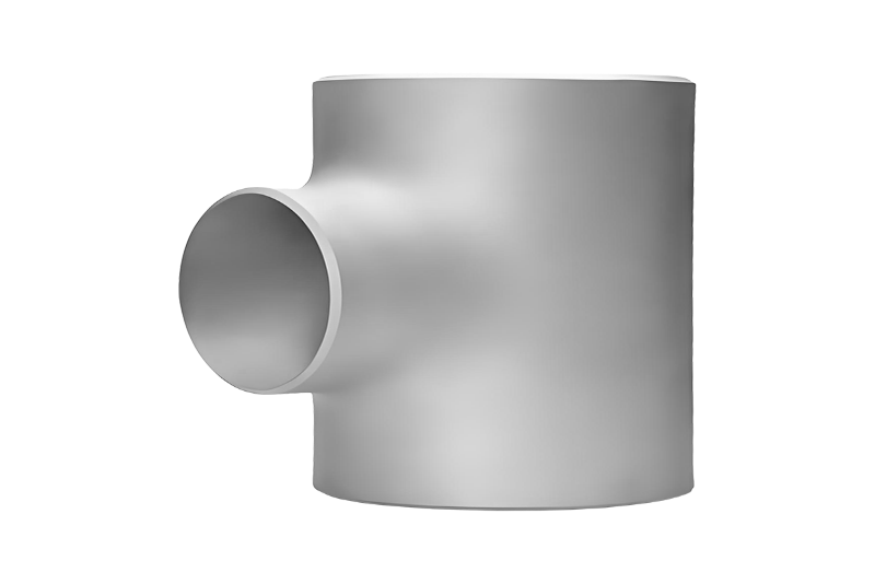
Material Selection for Butt Weld Fittings Choosing the right material is the first step in selecting...
Home / News / Industry News / Pipe Fittings Identification Chart: How to Identify Fittings by Type & Symbol
Pipe Fittings Identification Chart: How to Identify Fittings by Type & Symbol

Content
- 1 Why a Fittings Identification Chart Earns Its Place
- 2 Start With the Connection, Not the Shape
- 3 Butt Weld Fittings: The Heart of Any Identification Chart
- 4 Threaded, Socket Welded and Other Forged Fittings
- 5 Flanges: Read the Face and the Bore
- 6 Sizes, Schedules and Wall Thickness
- 7 What the Stamping Tells You
- 8 Three Identification Mistakes We See Most Often
A pipe rack rarely comes with labels. By the time a fitting needs replacing, the original drawing may be filed away, the paint has flaked off the markings, and the line is still running hot. That is usually the moment someone reaches for an identification pipe fittings chart, not to study theory but to answer one very practical question: what exactly is this part? After more than thirty years of manufacturing fittings in Jiangyin, we have talked through that question with engineers, fitters and buyers on five continents, often while standing next to the part itself. This guide turns those conversations into charts you can read at a glance on site.
Why a Fittings Identification Chart Earns Its Place
Fittings are the least glamorous components in a piping system and the easiest to misread. A 90-degree elbow and a short-radius 45-degree elbow look similar at arm's length, and an eccentric reducer can pass for a concentric one until somebody checks which way the flat side faces. Those small misreadings carry real consequences. The wrong wall thickness changes the weld preparation. The wrong branch size changes flow distribution. A wrong material grade can fail in service long before its design life. An identification chart is simply a way of slowing down for thirty seconds before those decisions are made, and it usually pays for itself the first time it prevents a returned shipment or a re-cut spool.
Start With the Connection, Not the Shape
Experienced fitters work in the same order every time. Before measuring anything, they look at how the fitting joins the pipe, because the connection method tells you which standard, which pressure class and often which size range you are dealing with.
| Connection family | How to recognise it on site | Typical size range | Common standards |
|---|---|---|---|
| Butt weld | Plain bevelled ends, no threads or recess, matches pipe outside diameter | 1/2" to 72" (DN15 to DN1800) | ASME B16.9, B16.28, DIN 2605, JIS B2311 |
| Socket weld | A recessed bore the pipe slips into, fillet welded on the outside | 1/2" to 4" (DN15 to DN100) | ASME B16.11, MSS SP-79, SP-83, SP-95 |
| Threaded | Visible tapered threads, NPT or BSP, can be unscrewed | 1/2" to 4" (DN15 to DN100) | ASME B16.11, BS 3799 |
| Flanged | A bolted joint; the fitting itself is a flange with a bolt circle | 1/2" and larger | ASME B16.5, B16.47, EN 1092-1 |
That first glance removes most of the guesswork. Plain bevelled ends mean a butt weld fitting, so you read the chart in the B16.9 column. Visible threads mean the forged family, so you switch to ASME B16.11 and think in inches rather than millimetres. Only after the family is settled does it make sense to argue about radius, wall thickness or face type.
Butt Weld Fittings: The Heart of Any Identification Chart
Butt weld fittings make up the largest share of what moves through a process plant, and they are also the group most often confused with one another. The table below links the outline you see with the job the part performs.
| Fitting | What you see | Where it is used |
|---|---|---|
| 90-degree elbow | A sharp right-angle bend; radius is 1.5D long or 1D short | Standard direction change |
| 45-degree elbow | A gentler bend, roughly half of a right angle | Gradual direction change, reduced pressure loss |
| 180-degree return bend | A U shape with both ends facing the same way | Heat exchangers, reversal loops |
| Equal tee | Three openings, branch same size as the run | Branch take-off with matched bore |
| Reducing tee | Three openings, branch smaller than the run | Branch take-off with reduced bore |
| Cross | Four openings, two runs intersecting | Manifolds, multi-directional flow |
| Concentric reducer | A cone with both ends on the same centreline | Vertical lines, general size change |
| Eccentric reducer | A cone with one flat side, bores offset | Pump inlets, horizontal lines, drainage |
| Cap | A dome-shaped end closure | Line termination, future tie-in points |
| Stub end | A short flared piece paired with a backing flange | Rotating joints, frequent dismantling |
The elbow is the part buyers ask about most, partly because its radius is easy to mismeasure and partly because a short-radius elbow can be mistaken for a long-radius one when the pipe is already in place. If you would like the dimensional reference for that single item, our page on the butt weld 90 degree elbow lists the centre-to-end figures by size.
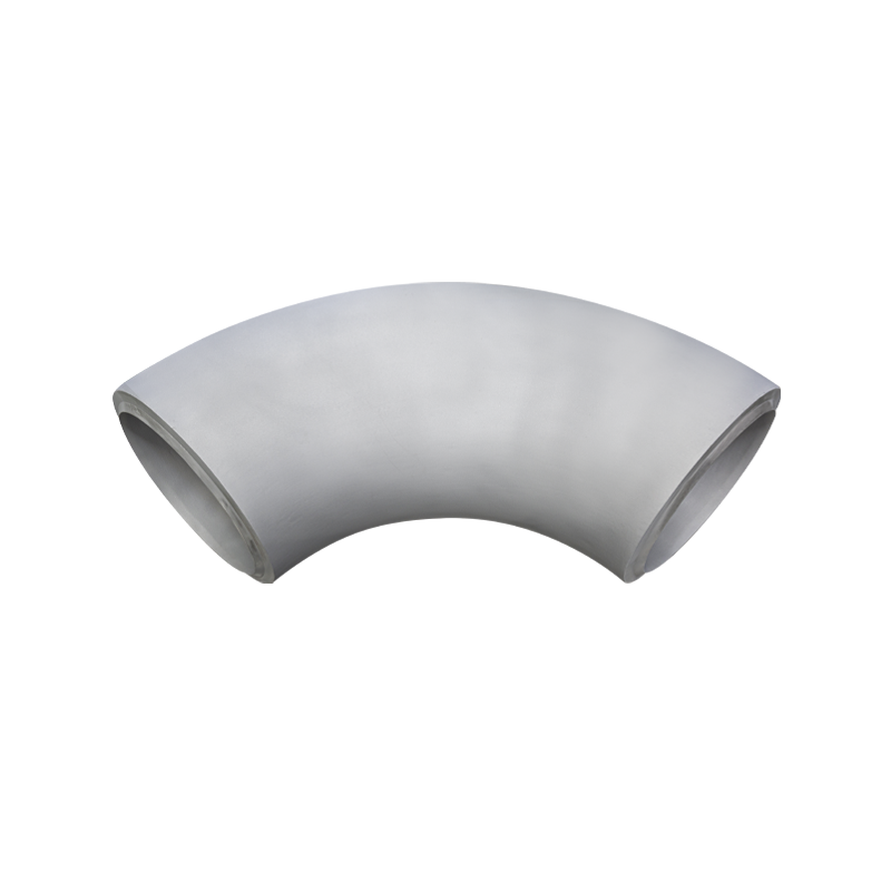 Butt Weld 90 Degree Elbow with Long and Short Radius OptionsProduct page lists DN15–DN3800 sizes, long-radius and short-radius types, and centre-to-end data useful when matching ASME B16.9 or EN dimensions before cutting spools.View Product →
It also helps to keep the governing standard in view. On most export projects the butt weld family is ordered against ASME B16.9 butt weld fittings, while European specifications may call for DIN or EN dimensions that differ by a few millimetres in centre-to-end length. Those few millimetres matter when a spool has already been cut.
Threaded, Socket Welded and Other Forged Fittings
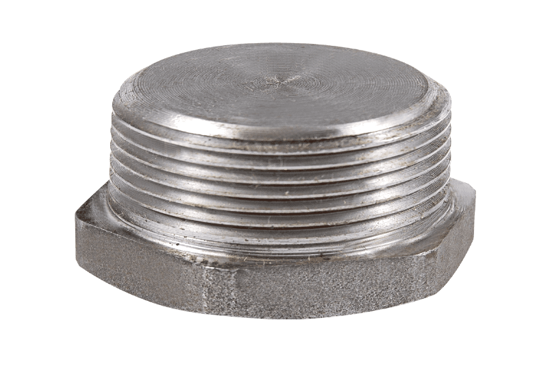
Below roughly four inches, welded and threaded fittings give way to forged construction, and the identification chart changes character. Forged parts are compact, thick-walled and shaped by pressing or machining rather than by forming from plate or seamless tube. In this range you will meet the forged 90-degree threaded elbow, the forged equal tee, branch outlets, socket welding caps, square head plugs, threaded couplings and unions.
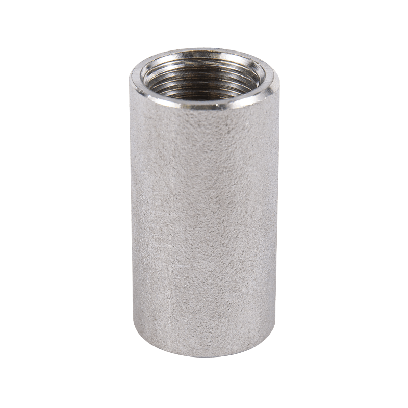 Forged Thread Coupling for Small-Diameter Piping ConnectionsIn small-diameter forged fittings, this straight threaded coupling joins pipe sections without welding, with machined threads available in carbon or stainless steel.View Product →
Identification here is usually a matter of bore and thread. A coupling is a short cylinder with threads at both ends and no bend, while an elbow has the same threaded ends but a visible right angle. A cap closes the line, and a plug screws into a fitting rather than onto a pipe, which is why the two are often mistaken for each other in a store room. Our overview of forged threaded and socket weld fittings groups these parts by shape so that the correct one is easier to pick.
Flanges: Read the Face and the Bore
Flanges are the part of the chart where people look at the outside and forget the inside. The outline tells you how the flange attaches to the pipe; the face tells you how it seals; the bore tells you which schedule it suits.
| Flange type | Recognise it by | Typical service |
|---|---|---|
| Weld neck | Long tapered hub, butt welded to the pipe | High pressure, high temperature, cyclic loading |
| Slip-on | Pipe passes straight through, two fillet welds | General service, lower pressure |
| Blind | Solid disc, no bore at all | Isolation, line blanks, maintenance |
| Threaded | Internal threads, no weld preparation | Small bore, non-welded systems |
| Socket weld | Recessed bore for the pipe, single fillet weld | Small bore, higher pressure |
| Lap joint | Used with a stub end, no weld contact with the face | Joints taken apart often |
| Plate / flat welding | Flat plate with a bore and bolt holes | Water, utilities, low pressure |
The gasket face is the second half of the story. A raised face is the default on most ASME flanges, a flat face suits cast iron or plastic mating equipment, and a ring type joint is reserved for high pressure gas where a metal ring seats in a grooved face. Our weld neck flange range shows how the hub length changes from one pressure class to the next.
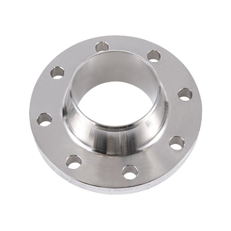 Weld Neck Flange for High-Pressure High-Temperature PipingButt-welded flange with tapered neck suits high-pressure, high-temperature lines; the raised-face sealing surface and hub length should be matched to pressure class and pipe schedule.View Product →
Sizes, Schedules and Wall Thickness
Nominal size is the most misread number on any chart. Nominal pipe size is not an actual outside diameter once you pass 12 inches, and DN values are nominal rather than millimetre measurements. Wall thickness is a separate variable again, chosen by schedule or by a designated thickness such as 10 mm or 14 mm on heavy-wall lines. This is why a six-inch elbow is never simply a six-inch elbow: the bore must match the pipe schedule, or the weld root will not line up. When a line is being replaced rather than rebuilt, the safest habit is to note the outside diameter, the wall thickness and the centre-to-end distance, then match all three against the chart before ordering.
What the Stamping Tells You
Almost every fitting carries a heat number, a size, a wall thickness and a material grade stamped or stencilled on the body. Reading those marks is faster and more reliable than any measurement:
- ASTM A234 WPB marks carbon steel butt weld fittings for ordinary service.
- WP304, WP316L and WP321H indicate stainless grades, with the H suffix denoting higher carbon for elevated temperature strength.
- WPL6 identifies low temperature carbon steel, chosen for service below freezing.
- WP91 and F91 point to alloy steel for high temperature steam on power plant lines.
- S32205 and S32750 stand for duplex and super duplex stainless, common in seawater and chemical duty.
- Inconel 625, 718 and titanium Grade 2 appear on specialised corrosion or high purity services.
If a marking has been painted over, the heat number can usually be traced back through the mill certificate, which confirms the chemistry and the mechanical properties in one step.
Three Identification Mistakes We See Most Often
- Measuring an elbow radius from the outside of the bend. Radius is taken to the centreline, so an external measurement always overstates it and can turn a short-radius part into a long-radius one on paper.
- Assuming every tee is equal. Branch size, branch angle and whether the branch is reinforced all change performance, and a lateral tee does a different job from a standard one.
- Trusting the outline and ignoring the material. Two fittings with the same geometry can look identical and behave completely differently in a low temperature or sour service line.
A chart is a starting point rather than a substitute for judgement. When a line matters, walk out to the rack with the chart in hand, check the connection, the bore, the wall thickness and the marking, and write all four down before calling anyone. It takes ten minutes and prevents most of the rework we are asked to help fix. If the answer is still unclear, our team is glad to work through it with you, whether the part came from our workshop in Jiangyin or from somewhere else entirely.
Latest News
News And Blogs
Stay Informed About Our Recent Events