Language
 English
 中文简体
中文简体 русский
 Español
 عربى
عربى
Material Selection for Butt Weld Fittings Choosing the right material is the first step in selecting...
Home / News / Industry News / What Are Socket Weld Flanges and How Do You Choose the Right Material?
What Are Socket Weld Flanges and How Do You Choose the Right Material?

Content
- 1 What a Socket Weld Flange Is and How It Differs From Other Flange Types
- 2 Key Features That Define Socket Weld Flange Performance
- 3 Common Applications for Socket Weld Flanges
- 4 Material Options and How to Choose Between Them
- 5 Installation and Welding Best Practices
- 6 Comparing Socket Weld Flanges to Slip-On and Weld Neck Flanges
- 7 Inspection and Quality Checks Before Installation
What a Socket Weld Flange Is and How It Differs From Other Flange Types
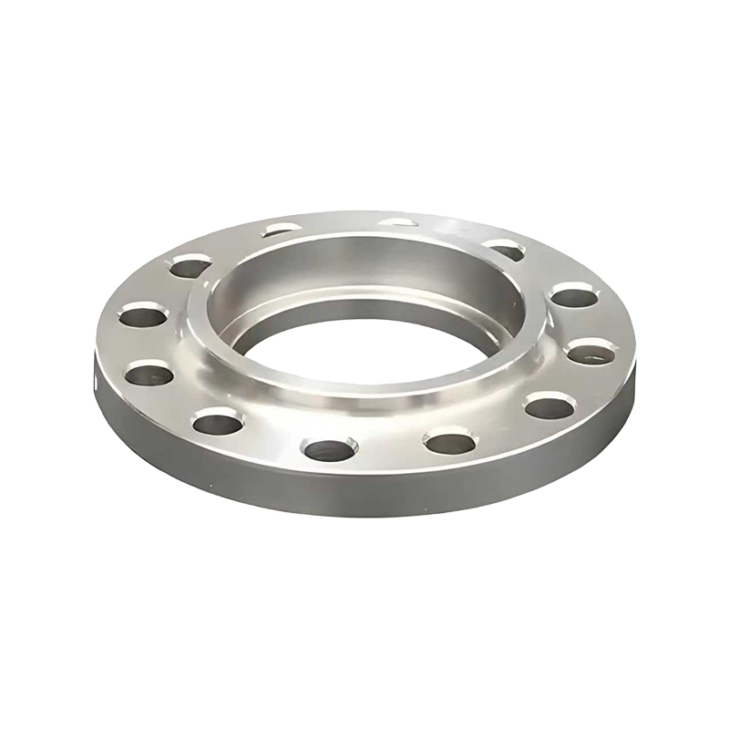
A socket weld flange is designed with a recessed bore on one side that allows a pipe to be inserted directly into the flange before a single fillet weld is applied around the outside of the joint. This differs from a weld neck flange, which requires the pipe to be butt-welded to a tapered hub, and from a slip-on flange, which slides over the pipe and is welded both inside and outside the joint. The socket weld design eliminates the need for precise beveling on the pipe end, which makes it faster to fabricate and easier to align during installation compared to butt-weld connections.
Because the weld in a socket weld flange only needs to join the outer pipe surface to the flange socket, rather than penetrating through the full wall thickness of the pipe, this flange type is generally reserved for smaller pipe diameters, typically 2 inches and below, where full penetration welding is less critical to overall joint strength. This makes socket weld flanges a practical choice for smaller-bore piping systems where speed of installation and joint reliability both matter.
Key Features That Define Socket Weld Flange Performance
Several specific design details separate a properly performing socket weld flange from one that develops leaks or stress cracking after a short period in service. Understanding these features helps engineers and procurement teams specify the right flange for a given system rather than relying on a generic catalog listing.
Bore and Socket Depth Tolerances
The socket bore must be machined to match the outside diameter of the pipe it will receive, with a small clearance gap built in to allow the pipe to seat fully without binding. Industry standards specify a small gap, typically around 1.6 millimeters, left between the end of the inserted pipe and the bottom of the socket before welding. This gap is intentional and accounts for thermal expansion during the welding process and in-service temperature changes, since welding the pipe end flush against the socket bottom can lead to cracking as the joint expands and contracts under heat cycling.
Pressure Class Ratings
Socket weld flanges are manufactured to standard pressure classes, most commonly Class 150, 300, 600, 900, 1500, and 2500 under ASME B16.5 specifications, with higher numbers indicating greater pressure-handling capability at a given temperature. Selecting the correct pressure class requires matching the flange rating not just to the system's normal operating pressure but to the maximum pressure that could occur during a surge event, a startup condition, or a temporary upset in the process. Choosing a class that only covers normal operating conditions without margin for these events is one of the more common specification mistakes in piping system design.
Common Applications for Socket Weld Flanges
Socket weld flanges are widely used across industries that rely on small-bore, high-pressure piping where leak-tight joints are critical but full butt-weld fabrication would be unnecessarily time-consuming. They are particularly common in instrumentation lines, hydraulic systems, and steam piping in smaller diameters where vibration resistance and joint reliability matter more than accommodating very large flow volumes.
- High-pressure hydraulic systems in industrial machinery and offshore platforms where vibration resistance is important.
- Instrumentation and sensor connections in process plants where small-bore piping carries pressure or temperature readings.
- Steam distribution lines in smaller diameters where thermal cycling resistance matters more than large flow capacity.
- Chemical processing skids that require leak-tight joints in compact piping arrangements with limited welding access.
- Shipbuilding and marine piping systems where space constraints favor smaller, easier-to-weld flange connections.
Material Options and How to Choose Between Them
Socket weld flanges are produced in a range of materials, and selecting the right one depends on the fluid being carried, the operating temperature, and the level of corrosion resistance required. Carbon steel remains the most common and economical choice for general industrial service where the fluid is non-corrosive and temperatures stay within moderate ranges. Stainless steel grades, particularly 304 and 316, are chosen when the system carries corrosive chemicals, food-grade fluids, or operates in marine environments where chloride exposure accelerates corrosion in lower-grade materials.
| Material | Typical Service Condition | Relative Cost |
| Carbon Steel (A105) | General industrial, non-corrosive fluids | Low |
| Stainless Steel 304 | Food, beverage, mild corrosive service | Moderate |
| Stainless Steel 316 | Marine, chemical, chloride exposure | High |
| Alloy Steel (A182 F11/F22) | High-temperature steam and refinery service | High |
Installation and Welding Best Practices
Proper installation of a socket weld flange begins with confirming that the pipe end is cut square and free of burrs, since uneven edges can create stress concentration points once the fillet weld is applied. The pipe should be inserted into the socket and then pulled back slightly to create the required expansion gap before tack welding begins, rather than welding with the pipe pushed fully to the bottom of the socket. Preheating may be required for thicker-walled pipe or certain alloy steel materials to reduce the risk of cracking during cooling, and welders should follow the specific procedure outlined in the project's welding procedure specification rather than assuming a generic fillet weld approach is sufficient.
After welding, visual inspection should confirm a uniform fillet weld profile around the entire circumference without undercut, porosity, or incomplete fusion at any point. For critical service applications, radiographic or dye penetrant testing may be specified to confirm weld integrity before the piping system is pressure tested and put into service.
Comparing Socket Weld Flanges to Slip-On and Weld Neck Flanges
Choosing between socket weld, slip-on, and weld neck flanges depends on pipe size, pressure requirements, and fabrication speed. Slip-on flanges are easier to align during installation since the pipe slides through the flange bore rather than into a recessed socket, but they generally have lower pressure ratings and fatigue resistance compared to socket weld designs at the same nominal size. Weld neck flanges offer the highest strength and best resistance to bending stress due to their tapered hub design and full penetration weld, making them the preferred choice for high-pressure, large-diameter, or critical service piping, though they require more precise pipe beveling and longer welding time than socket weld connections.
For small-bore piping under 2 inches in diameter, socket weld flanges typically offer the best combination of strength, leak resistance, and installation speed, which is why they remain the standard choice across many industrial piping specifications for that size range despite weld neck flanges technically offering superior strength in larger sizes.
Inspection and Quality Checks Before Installation
Before a socket weld flange is installed into a piping system, it should be checked against its material test certificate to confirm the chemical composition and mechanical properties match the specified grade, since substituting an incorrect material grade can compromise the entire system's pressure rating. The flange's bore should be measured against the actual pipe outside diameter to confirm proper fit, since manufacturing tolerances can occasionally result in a bore that is too tight or too loose for the intended pipe schedule.
- Confirm the flange's pressure class rating matches the system's maximum design pressure, not just its normal operating pressure.
- Check the bore diameter against the pipe schedule being used to ensure proper clearance for insertion and welding.
- Inspect the flange face for flatness and surface finish, since an uneven gasket face can lead to leaks after assembly.
- Verify markings on the flange, including material grade, pressure class, and manufacturer identification, against the purchase order specification.
Latest News
News And Blogs
Stay Informed About Our Recent Events