English
 中文简体
中文简体 русский
 Español
 عربى
عربى
Material Selection for Butt Weld Fittings Choosing the right material is the first step in selecting...
What Are the Different Flange Types Used in Piping Systems?

Content
- 1 What Is a Piping Flange and Why Does Type Selection Matter?
- 2 The Main Flange Types Used in Piping
- 3 Flange Type Comparison by Key Criteria
- 4 Flange Face Types and Their Role in Joint Sealing
- 5 Flange Pressure Classes and What They Mean
- 6 Common Flange Materials and Their Applications
- 7 How to Choose the Right Flange for Your Piping System
- 8 Conclusion
Flanges are among the most fundamental components in any piping system, providing the mechanical joints that connect pipes, valves, pumps, and equipment in a way that is both structurally secure and — critically — removable for inspection, maintenance, or modification. In industries ranging from oil and gas and petrochemicals to water treatment, pharmaceuticals, and power generation, the correct selection of flange type, pressure class, facing, and material is as important as the pipe specification itself. A mismatched or incorrectly rated flange is a potential leak point, a regulatory compliance failure, and in high-pressure or high-temperature service, a serious safety hazard. This article covers the principal flange types used in piping systems, their engineering characteristics, applicable standards, and the practical criteria that guide correct flange selection.
What Is a Piping Flange and Why Does Type Selection Matter?
A piping flange is a disc, ring, or collar forged, cast, or machined from metal that is attached to a pipe end, valve body, or equipment nozzle and bolted to a mating flange to form a pressure-tight joint. The joint is sealed by a gasket compressed between the two flange faces by the clamping force of the bolts. The flange transfers mechanical loads between connected elements — including internal pressure, thermal expansion forces, weight loads, and vibration — while allowing the joint to be disassembled without cutting or welding.
Flange type selection matters because different types are suited to fundamentally different connection methods, pressure and temperature service conditions, pipe wall thicknesses, and ease of installation and disassembly. Using a slip-on flange in a high-pressure steam line, or a socket weld flange on a large-bore pipe, creates mismatches between the flange's structural capability and the demands placed on it. The governing standards — most commonly ASME B16.5, ASME B16.47, EN 1092-1, and API 6A — define dimensional, pressure class, and material requirements for each flange type, and compliance with these standards is mandatory in most regulated industries.
The Main Flange Types Used in Piping
Each flange type has a distinct method of attachment to the pipe and a specific set of structural characteristics. The seven types described below cover the vast majority of flanged joints encountered in industrial and commercial piping systems.
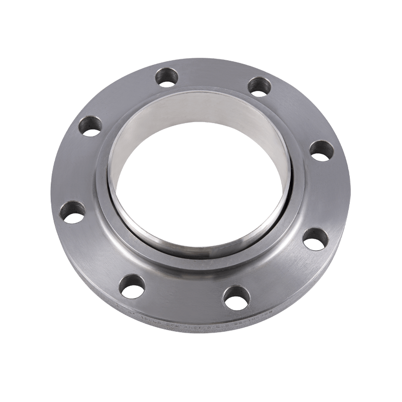
Weld Neck Flange
The weld neck flange is the most structurally robust and widely specified flange type for high-pressure, high-temperature, and cyclic service applications. It features a long, tapered hub that transitions gradually from the flange body to the pipe wall thickness, distributing stress evenly and minimizing the stress concentration at the weld joint. The flange is attached to the pipe by a full penetration butt weld, which provides the strongest possible joint integrity and allows radiographic examination of the weld for quality verification. Weld neck flanges are the standard specification in critical service lines in oil and gas, power generation, and chemical processing. Their higher cost and greater installation time compared to other types are justified by the superior mechanical performance and long-term reliability they deliver in demanding service conditions.
Slip-On Flange
The slip-on flange slides over the outside of the pipe and is attached with two fillet welds — one at the hub face and one at the back of the flange bore. Its bore is slightly larger than the pipe outside diameter, allowing the pipe to be inserted before welding, which simplifies alignment during installation. Slip-on flanges are lower in cost and easier to fit than weld neck flanges, making them popular in utility piping, low-pressure systems, and non-critical service lines. However, their structural strength is lower than weld neck flanges — typically rated at approximately two-thirds of the weld neck equivalent under the same pressure class — because the fillet welds do not provide full pipe wall penetration. They are generally limited to ASME Class 150 and 300 service in non-critical applications.
Socket Weld Flange
Socket weld flanges are used exclusively on small-bore piping, typically 2 inches (50 mm) nominal bore and below. The pipe is inserted into a socket machined into the flange bore and a fillet weld is applied at the hub. A small gap of approximately 1.6 mm is deliberately left between the pipe end and the socket shoulder before welding to allow for thermal expansion and prevent weld cracking. Socket weld flanges provide a cleaner interior bore than slip-on flanges for small pipe sizes, which reduces turbulence and erosion in high-velocity service. They are used in high-pressure hydraulic lines, instrument connections, and chemical injection piping where small bore integrity is critical. They are not suitable for slurry services or corrosive fluids where the crevice at the socket-to-pipe gap could trap material.
Threaded Flange
Threaded flanges connect to the pipe via a tapered or parallel internal thread rather than welding, making them the only common flange type that requires no welding for attachment. They are used in low-pressure utility systems, instrument connections, and applications in non-hazardous services where the presence of flammable or explosive gases makes welding operations impractical. Threaded flanges are mechanically weaker than welded types and are susceptible to leakage under thermal cycling or vibration, which progressively loosens the threaded engagement. Many specifications prohibit their use in services above 300°F (150°C) or in flammable gas and liquid service for this reason. In environments where welding restrictions apply but higher integrity is required, a threaded-and-seal-welded configuration — applying a seal weld over the threaded joint — provides improved reliability.
Blind Flange
A blind flange is a solid disc with no bore that is used to close off the end of a pipe, nozzle, or vessel opening. It is bolted against a mating flange face with a gasket, creating a fully pressure-rated closure that can be removed when access to the line is required. Blind flanges are used at pipe ends for future expansion connections, at vessel inspection openings, at pressure test points, and as permanent end closures on redundant branch connections. They must be rated to the full system pressure class and are subject to significant bending stress from internal pressure acting on their unsupported face area, which is why blind flange wall thickness increases substantially with larger bore sizes and higher pressure classes.
Lap Joint Flange
The lap joint flange is used in conjunction with a stub end fitting — a short section of pipe with a machined radius at one end that provides the sealing face. The lap joint flange slides freely over the stub end and is not welded to the pipe; instead, the stub end is butt welded to the pipe and the loose flange backs up against the stub end radius. This arrangement allows the flange to rotate freely around the pipe, which greatly simplifies bolt hole alignment during installation, particularly in congested areas or where equipment connections are not precisely positioned. Lap joint flanges are also economically advantageous in expensive alloy piping systems because only the stub end — the component in contact with the fluid — needs to be manufactured from the alloy material, while the backing flange can be standard carbon steel.
Orifice Flange
Orifice flanges are a specialized variant of the weld neck or slip-on flange design that incorporate tapped pressure tapping holes machined into the flange body on either side of an orifice plate. The orifice plate — a precision-drilled disc — is clamped between the pair of orifice flanges and creates a calibrated pressure differential as fluid passes through the restricted bore. This differential pressure is measured through the tapping holes and used to calculate volumetric or mass flow rate. Orifice flange assemblies are a standard flow measurement technology in oil and gas, chemical processing, and water treatment applications, and their dimensional and machining requirements are specified in ASME MFC-3M and ISO 5167.
Flange Type Comparison by Key Criteria
The following table provides a practical comparison of the main flange types across the criteria most relevant to selection decisions in industrial piping design.
| Flange Type | Attachment Method | Pressure Suitability | Typical Use Case |
| Weld Neck | Butt weld | All classes, critical service | High pressure, high temperature lines |
| Slip-On | Double fillet weld | Class 150–300, non-critical | Utility and low-pressure piping |
| Socket Weld | Fillet weld into socket | High pressure, small bore only | Instrument, hydraulic, injection lines |
| Threaded | Pipe thread, no weld | Low pressure, non-hazardous only | No-weld zones, utility services |
| Blind | Bolted (no pipe attachment) | All classes | End closures, future connections |
| Lap Joint | Loose over stub end | Moderate pressure | Alloy piping, frequent dismantling |
Flange Face Types and Their Role in Joint Sealing
The flange face is the machined surface that contacts the gasket and creates the pressure seal. Selecting the wrong face type for a given service condition or gasket material is a common cause of joint leakage. The four most widely used face types in industrial piping each have distinct sealing mechanisms and application ranges.
Raised Face (RF)
The raised face is the most common flange face type in process piping and the default face type for ASME B16.5 flanges from Class 150 through Class 2500. The seating surface is a raised ring — typically 1.6 mm high for Class 150 and 300, and 6.4 mm high for Class 600 and above — that concentrates bolt clamping force onto the gasket area. The standard surface finish for raised face flanges is a concentric or spiral serrated finish with a roughness of 3.2 to 6.3 µm Ra, which provides mechanical interlock with soft and semi-metallic gaskets. Raised face flanges are compatible with the full range of flat, spiral wound, and ring type gaskets used in general process service.
Flat Face (FF)
The flat face flange has its seating surface flush with the flange body face with no raised area. It is used when mating against flanged equipment — such as cast iron valves, pumps, and non-metallic equipment — where a raised face would impose uneven bending loads on the mating component and risk cracking it. Flat face flanges use full-face gaskets that extend to the bolt circle and beyond, distributing the bolt load across the entire flange face and preventing the edge-loading that a ring gasket would create on a brittle mating flange.
Ring Type Joint (RTJ)
Ring type joint flanges have a precision-machined trapezoidal or oval groove machined into the flange face into which a solid metal ring gasket — typically soft iron, low carbon steel, 316 stainless steel, or Inconel — is seated. As the bolts are tightened, the ring gasket is plastically deformed into the groove, creating an extremely high-integrity metal-to-metal seal. RTJ joints are specified for high-pressure, high-temperature, and sour gas service where the reliability demands exceed what soft or semi-metallic gaskets can provide. They are standard in wellhead, subsea, and high-integrity process piping and require precision machining of both the groove and the ring to achieve their rated performance.
Tongue and Groove (T&G)
Tongue and groove flanges are mated pairs where one flange face has a raised tongue and the other has a matching groove machined into the face. The gasket seats entirely within the groove, where it is constrained on all sides, preventing gasket blowout under surge pressure conditions. T&G joints provide superior gasket retention and are used in heat exchanger covers, valve bonnets, and high-integrity process connections where gasket blowout risk must be minimized. Because the two halves must be matched pairs, tongue and groove flanges are not interchangeable with standard raised face flanges of the same size and pressure class.
Flange Pressure Classes and What They Mean
Under ASME B16.5 — the dominant standard for pipe flanges in North America and widely referenced internationally — flanges are designated by pressure class: 150, 300, 600, 900, 1500, and 2500. These class numbers do not represent a fixed pressure rating; rather, they define the pressure-temperature rating of the flange, which decreases as temperature increases due to the reduction in material yield strength at elevated temperatures.
For example, a Class 300 flange in ASTM A105 carbon steel is rated at approximately 51.1 bar (740 psi) at ambient temperature, but only 14.4 bar (210 psi) at 450°C (850°F). The correct pressure class for a given service must therefore be selected based on both the maximum operating pressure and the maximum operating temperature, using the pressure-temperature rating tables in ASME B16.5 or the equivalent EN 1092-1 tables for European standard flanges. Undersizing the pressure class for the actual service temperature is one of the most consequential errors in flange specification.
Common Flange Materials and Their Applications
Flange material selection must be compatible with both the process fluid and the external environment, and must maintain adequate mechanical properties across the full operating temperature range.
- ASTM A105 (Carbon Steel): The standard material for carbon steel flanges in general process service up to approximately 425°C. Used in oil and gas, water, steam, and non-corrosive chemical service. Low cost and widely available in all pressure classes and types.
- ASTM A182 F316/F316L (Stainless Steel): Used for corrosive chemical service, food and pharmaceutical applications, and marine environments. Grade 316 provides good general corrosion resistance; 316L (low carbon) is specified where sensitization from welding heat must be prevented.
- ASTM A182 F11 / F22 (Alloy Steel): Chromium-molybdenum alloy steels used in high-temperature service above 425°C in steam generation, reformer, and fired heater piping where carbon steel loses mechanical strength.
- ASTM A350 LF2 (Low Temperature Carbon Steel): Impact-tested carbon steel for cryogenic and low-temperature service down to -46°C, used in LNG facilities, refrigeration systems, and cold climate outdoor piping.
- Duplex and Super Duplex Stainless Steel (F51, F53): Used in highly corrosive environments including seawater service, subsea piping, and chloride-rich chemical streams where standard austenitic stainless steels would suffer stress corrosion cracking or pitting corrosion.
How to Choose the Right Flange for Your Piping System
Correct flange selection requires a systematic evaluation of multiple parameters in combination rather than optimizing for any single criterion such as cost or availability.
- Define the service conditions precisely: Establish the maximum operating pressure, maximum operating temperature, fluid composition including any corrosive constituents, and the cyclic or dynamic loading character of the service before selecting any flange component.
- Select flange type based on structural requirements: Use weld neck flanges for all high-pressure, high-temperature, cyclic, or hazardous service lines. Use slip-on flanges only in utility or low-criticality service where cost reduction is justified and the lower structural integrity is acceptable within the applicable code.
- Determine pressure class from P-T rating tables: Look up the pressure-temperature rating for the chosen material in ASME B16.5 or EN 1092-1 at the actual service temperature, not ambient temperature. Apply the appropriate safety factor required by the applicable design code.
- Match face type to gasket selection and mating equipment: Use raised face with spiral wound or ring gaskets for general process service. Use flat face when mating against cast iron or non-metallic flanged equipment. Use RTJ for high-pressure or sour service where metal-to-metal sealing is required.
- Verify material compatibility: Confirm that the flange material is compatible with both the process fluid — considering corrosion, erosion, and stress corrosion cracking — and the external environment, including insulation under cladding corrosion risk and cathodic protection compatibility for buried or submerged service.
Conclusion
Flanges for piping systems encompass a far wider range of engineering decisions than their seemingly straightforward role as pipe connectors might suggest. The choice between a weld neck, slip-on, socket weld, threaded, blind, lap joint, or orifice flange determines the structural integrity of the joint, the ease of installation and maintenance, and the suitability of the connection for the specific service environment. Combined with the correct face type for the gasket and mating equipment, the appropriate pressure class for the operating temperature, and a material specification matched to the process fluid and environmental conditions, the right flange selection ensures a piping system that performs safely and reliably throughout its design life without unnecessary maintenance burden or failure risk.
Latest News
News And Blogs
Stay Informed About Our Recent Events