English
 中文简体
中文简体 русский
 Español
 عربى
عربى
Material Selection for Butt Weld Fittings Choosing the right material is the first step in selecting...
What Flange Size Do I Need? A Practical Sizing Guide

Content
- 1 Why Getting Flange Size Right Matters
- 2 Start with Nominal Pipe Size (NPS or DN)
- 3 Understanding Pressure Class and Why It Affects Physical Size
- 4 Flange Dimensions Reference: NPS vs Outer Diameter and Bolt Circle
- 5 Choosing the Right Flange Face Type for Your Application
- 6 Flange Types: Matching the Connection Type to Your Piping System
- 7 Step-by-Step: How to Confirm the Flange Size You Need
Why Getting Flange Size Right Matters
Selecting the correct flange size is one of the most consequential decisions in any piping system design or repair project. A flange that is too small for the pipe bore restricts flow and creates turbulence; one with the wrong bolt circle diameter will not align with its mating flange, making assembly impossible without costly modifications. Worse, a flange selected for the wrong pressure class can fail catastrophically under operating conditions, resulting in leaks, system shutdowns, or safety incidents. The good news is that flange sizing follows well-established standards, and once you understand the key parameters — nominal pipe size, pressure class, facing type, and material — selecting the right flange becomes a straightforward process.
This guide addresses the practical question of what flange size you need by walking through each sizing variable in sequence, providing reference data drawn from the most widely used international standards (ASME B16.5, ASME B16.47, EN 1092-1, and DIN), and flagging the most common mistakes that lead to mismatched or underperforming flange selections.
Start with Nominal Pipe Size (NPS or DN)
The foundation of any flange size selection is the Nominal Pipe Size (NPS) in North American practice, or Nominal Diameter (DN) in the metric system used across Europe, Asia, and much of the rest of the world. It is critical to understand from the outset that these nominal sizes are reference designations — they do not directly correspond to any measured dimension of the pipe or flange. A 2-inch (NPS 2) pipe, for instance, has an actual outside diameter of 2.375 inches, not 2 inches. The nominal size exists purely as a convenient label for matching pipes, fittings, and flanges within the same system.
The flange bore — the inner diameter of the flange through which fluid passes — must match the inside diameter of the pipe it connects to. This is determined by the pipe's nominal size and its wall thickness schedule (Schedule 40, Schedule 80, and so on). A flange ordered as NPS 3, Schedule 40 will be bored to match the internal diameter of a standard Schedule 40 pipe of that nominal size. If you are connecting to a Schedule 80 pipe of the same nominal size, the bore will be different, and the flange must be specified accordingly or bored to size after purchase.
The NPS-to-DN conversion is direct and standardised: NPS 1 = DN 25, NPS 2 = DN 50, NPS 4 = DN 100, NPS 6 = DN 150, NPS 8 = DN 200, NPS 10 = DN 250, NPS 12 = DN 300. For sizes above NPS 24 (DN 600), flanges fall outside the scope of ASME B16.5 and are instead covered by ASME B16.47 (Series A and Series B), which governs large-diameter flanges up to NPS 60.
Understanding Pressure Class and Why It Affects Physical Size
A flange's pressure class (also called pressure rating or PN rating) defines the maximum allowable working pressure the flange can sustain at a given temperature. Under ASME B16.5, flanges are classified into seven pressure classes: Class 150, 300, 400, 600, 900, 1500, and 2500. Under the European EN/DIN system, the equivalent designation is the PN (Pressure Nominale) rating: PN 6, PN 10, PN 16, PN 25, PN 40, PN 63, PN 100, and higher.
The pressure class has a direct impact on the physical dimensions of the flange — not just its pressure capacity. A higher-class flange of the same nominal pipe size will have a larger outer diameter, more bolt holes, larger bolt hole diameters, and a greater flange thickness than a lower-class flange. This means that a Class 300 flange and a Class 150 flange of the same NPS are not interchangeable, even though they connect to the same pipe. Their bolt circles and outer diameters differ, so they cannot be bolted together. Always ensure that both mating flanges are of identical NPS and pressure class.
To determine what pressure class you need, compare your system's maximum operating pressure and temperature against the pressure-temperature (P-T) rating tables published in ASME B16.5 for the relevant material group. A Class 150 carbon steel flange (Group 1.1 material) is rated at 285 psi (19.6 bar) at 100°F but derated to 200 psi at 400°F. If your system operates at 500 psi and 200°F, a Class 150 flange is inadequate — you would need at least Class 300, which is rated at 740 psi at 200°F for the same material group. Never select pressure class based on nominal rating alone; always verify against the P-T tables for your specific material and operating temperature.
Flange Dimensions Reference: NPS vs Outer Diameter and Bolt Circle
The table below provides key dimensional data for ASME B16.5 flanges at Class 150 and Class 300 for common pipe sizes, enabling direct comparison of how pressure class scales the physical flange dimensions:
| NPS | Class 150 OD (in) | Class 150 Bolt Circle (in) | Class 150 No. of Bolts | Class 300 OD (in) | Class 300 Bolt Circle (in) | Class 300 No. of Bolts |
|---|---|---|---|---|---|---|
| 1 | 4.25 | 3.12 | 4 | 4.88 | 3.50 | 4 |
| 2 | 6.00 | 4.75 | 4 | 6.50 | 5.00 | 8 |
| 4 | 9.00 | 7.50 | 8 | 10.75 | 8.50 | 8 |
| 6 | 11.00 | 9.50 | 8 | 14.00 | 11.50 | 12 |
| 8 | 13.50 | 11.75 | 8 | 16.50 | 13.75 | 12 |
| 12 | 17.00 | 14.75 | 12 | 20.50 | 17.75 | 16 |
This table makes clear why pressure class cannot be treated as a minor detail. At NPS 6, the outer diameter difference between Class 150 and Class 300 is 3 inches, and the bolt count increases from 8 to 12. Specifying the wrong class requires complete disassembly and replacement, not a simple on-site adjustment.
Choosing the Right Flange Face Type for Your Application
The flange face is the sealing surface that contacts the gasket, and selecting the correct face type is just as important as getting the nominal size and pressure class right. The most common facing types and their appropriate applications are:
- Raised Face (RF): The most widely used facing type in process piping. A circular raised ring sits above the flange face, concentrating bolt load onto a smaller gasket area and improving sealing efficiency. Used with flat or spiral-wound gaskets. Standard for ASME Class 150 and above in most process applications.
- Flat Face (FF): The entire flange face is flush, with no raised ring. Required when connecting to cast iron or ductile iron equipment, where a raised face would concentrate stress and risk cracking the mating flange. Full-face gaskets are used with flat-face flanges. Never use a raised-face flange against a flat-face cast iron flange.
- Ring-Type Joint (RTJ): A machined groove on the flange face accepts a solid metal ring gasket (oval or octagonal cross-section). Provides the highest integrity seal and is used in high-pressure and high-temperature applications such as wellhead equipment, high-pressure steam, and refinery service. Class 600 and above commonly specify RTJ facing.
- Tongue and Groove (T&G): One flange has a raised tongue and the other a matching groove. The gasket is fully retained, making this facing type suitable for high-pressure applications and hazardous fluids where gasket blowout must be prevented. Common in pump covers and heat exchanger bonnets.
- Male and Female (M&F): Similar principle to T&G but with a wider sealing surface. One flange face is raised (male) and the other recessed (female). Used in high-pressure specialty applications and must always be paired — a male face cannot be bolted to a raised face or another male face.
Flange Types: Matching the Connection Type to Your Piping System
Beyond size, pressure class, and facing, the flange type defines how the flange physically connects to the pipe. Each type suits different pipe materials, installation conditions, and performance requirements.
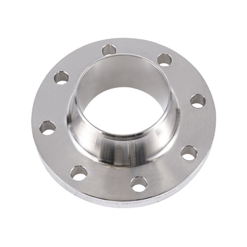
Weld Neck Flange
The weld neck flange features a long, tapered hub that is butt-welded to the pipe. The gradual taper distributes stress evenly between the flange and the pipe, making weld neck flanges the preferred choice for high-pressure, high-temperature, and cyclic loading applications. The bore of the flange must match the pipe bore precisely — which is why weld neck flanges must be specified with both NPS and pipe schedule. This type provides the strongest and most reliable flange-to-pipe joint available and is standard in critical process piping.
Slip-On Flange
The slip-on flange slides over the pipe and is fillet-welded both inside and outside. It is easier to align during installation than a weld neck flange and requires less precise pipe cut length, reducing fabrication time and cost. However, slip-on flanges have lower fatigue resistance and are not recommended for high-pressure, high-temperature, or cyclic service. They are appropriate for lower-pressure water, steam, and non-critical process lines where ease of installation is prioritised.
Socket Weld Flange
The pipe inserts into a socket in the flange body and is secured with a single fillet weld on the outside. Socket weld flanges are used for small-bore piping — typically NPS 2 and below — in high-pressure applications where butt welding small-diameter pipe is impractical. A small gap must be left between the pipe end and the socket bottom before welding to allow for thermal expansion and avoid stress cracking at the weld root.
Threaded Flange
The threaded flange screws onto a male-threaded pipe end without welding, making it suitable for installations where welding is prohibited — flammable atmospheres, field repairs, or non-weldable materials. Threaded flanges are limited to lower pressure classes (Class 150 and 300) and smaller pipe sizes (generally NPS 4 and below). They are not recommended for cyclic service or for fluids that cause crevice corrosion in the thread space.
Blind Flange
A blind flange has no bore — it is a solid disc used to close the end of a pipe, vessel nozzle, or valve. When selecting a blind flange, you need to match the NPS, pressure class, facing type, and material to the mating flange of the pipe or nozzle being closed. Blind flanges must be sized and rated to withstand the full system pressure applied to their face area, which increases rapidly with diameter — a 12-inch blind flange at Class 300 must resist over 80,000 pounds of force at rated pressure.
Step-by-Step: How to Confirm the Flange Size You Need
To avoid misspecification, work through the following confirmation checklist before placing any flange order:
- Identify the pipe nominal size and schedule — measure the pipe outside diameter and use a standard OD-to-NPS chart to confirm the nominal size. Record the wall thickness schedule, as this determines the flange bore for weld neck and socket weld types.
- Determine the required pressure class — identify the maximum operating pressure and maximum operating temperature of the system, then check the ASME B16.5 P-T rating table for the flange material group you are considering. Select the lowest pressure class that exceeds your maximum operating conditions with an adequate safety margin.
- Verify the mating flange standard and dimensions — if you are connecting to an existing flange, measure its outer diameter, bolt circle diameter, number of bolt holes, and bolt hole diameter. Match these against ASME B16.5 or EN 1092-1 tables to confirm the standard, NPS, and class before ordering a mating flange.
- Specify facing type and surface finish — confirm the facing type required by your gasket selection and service conditions. For raised face flanges, specify the surface finish (125–250 AARH for spiral-wound gaskets; 63–125 AARH for ring-type joints) to ensure proper sealing.
- Confirm material compatibility — select a flange material (carbon steel, stainless steel, duplex, alloy) compatible with both the process fluid and the operating temperature range. Material selection also affects the pressure-temperature rating, so always re-verify the P-T rating after choosing the material.
Following this sequence ensures that every parameter affecting flange performance is addressed before procurement, eliminating the most common causes of mismatched or underperforming flange installations. When in doubt — particularly for high-pressure, high-temperature, or hazardous fluid service — consult a qualified piping engineer and verify the specification against the applicable design code before ordering.
Latest News
News And Blogs
Stay Informed About Our Recent Events