Language
 English
 中文简体
中文简体 русский
 Español
 عربى
عربى
Material Selection for Butt Weld Fittings Choosing the right material is the first step in selecting...
Home / News / Industry News / Why Is the Weld Neck Flange the Most Trusted Connection for High-Pressure Piping Systems?
Why Is the Weld Neck Flange the Most Trusted Connection for High-Pressure Piping Systems?

Content
- 1 What Is a Weld Neck Flange and How Does It Work
- 2 Key Structural Advantages Over Other Flange Types
- 3 Face Types Available on Weld Neck Flanges
- 4 Pressure Class Ratings and What They Mean
- 5 Common Material Grades and Their Service Suitability
- 6 Installation Best Practices for Weld Neck Flanges
- 7 When to Choose a Weld Neck Flange Over Other Connection Types
What Is a Weld Neck Flange and How Does It Work
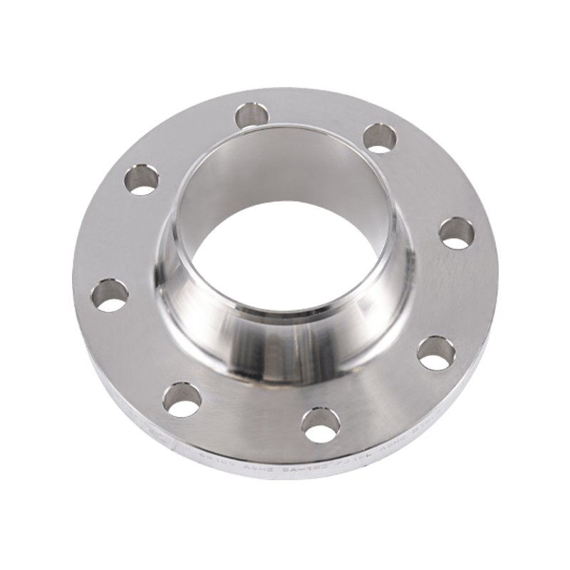
A weld neck flange is a type of pipe flange characterized by a long, tapered hub that extends from the flange face and transitions gradually into the pipe wall. This hub is butt-welded directly to the pipe, creating a full-penetration weld joint that becomes metallurgically continuous with the pipe itself. The tapered profile of the hub serves a specific engineering purpose: it distributes stress concentrations away from the weld zone and into the pipe body, significantly reducing the risk of fatigue failure under cyclic loading, thermal expansion, or high-pressure fluctuations. This structural behavior distinguishes the weld neck flange from slip-on, socket weld, and threaded alternatives, all of which create stress concentrations at or near the flange-to-pipe junction.
The flange face — the raised, flat, or ring-type joint surface on the front of the flange — mates with an identical face on a connecting flange or equipment nozzle. A gasket placed between the two faces provides the pressure seal when the bolted joint is tightened. The bore of the weld neck flange is matched precisely to the internal diameter of the pipe it connects to, ensuring unobstructed flow and eliminating any internal cavity or crevice that could trap fluid, promote corrosion, or disturb flow characteristics. This bore-matching feature, combined with the full-penetration weld, makes the weld neck flange the engineering-preferred choice for demanding service conditions across the oil and gas, petrochemical, power generation, and chemical processing industries.
Key Structural Advantages Over Other Flange Types
To appreciate why weld neck flanges command a premium price and remain the dominant choice in critical piping applications, it is necessary to understand concretely how they outperform alternative flange designs under real operating conditions.
- Stress distribution: The tapered hub transitions the wall thickness gradually from the flange body to the pipe wall, creating a smooth stress gradient rather than a sharp discontinuity. Finite element analysis of flange joints consistently shows that weld neck designs produce lower peak stresses at the critical weld location compared to slip-on flanges under equivalent loading conditions.
- Fatigue resistance: In applications with cyclic pressure, vibration, or thermal cycling — such as steam lines, hydraulic systems, and process reactors — the reduced stress concentration at the weld zone gives weld neck flanges significantly longer fatigue lives than other flange types.
- Leak integrity: The single full-penetration butt weld of a weld neck flange, when properly executed and examined, provides a joint integrity level that meets the most stringent pressure vessel and piping code requirements. Slip-on and socket weld flanges use fillet welds with inherently lower joint efficiency ratings.
- Radiographic inspectability: The butt weld between a weld neck flange and pipe is fully accessible for radiographic (X-ray) or ultrasonic testing, allowing 100% volumetric examination of the weld. This is a mandatory requirement in many high-pressure, high-temperature, and lethal service applications under ASME B31.3 and similar codes.
- Bore continuity: Because the flange bore is machined to match the pipe inside diameter, there is no step, ledge, or crevice at the weld joint interior. This eliminates a potential site for crevice corrosion, erosion, or flow-induced turbulence — all of which can be significant concerns in corrosive or high-velocity service.
Face Types Available on Weld Neck Flanges
The face configuration of a weld neck flange determines the type of gasket that can be used and significantly affects the sealing performance of the bolted joint. Selecting the correct face type is not merely a dimensional choice — it directly impacts system integrity under pressure and temperature.
Raised Face (RF)
The raised face is the most common face type in general industrial piping. A circular raised platform — typically 1.6mm high for Class 150 and 300 flanges, and 6.4mm for Class 400 and above — concentrates bolt load onto a relatively small gasket area, improving sealing efficiency with flat or spiral wound gaskets. The raised face surface is finished with serrated concentric or phonographic grooves that bite into the gasket material and resist gasket blowout under pressure surges.
Flat Face (FF)
The flat face type has a sealing surface that is flush with the flange back face, covering the entire flange face including the bolt holes. Flat face flanges are used when mating to cast iron or non-metallic flanged equipment where the uneven bolt load of a raised face connection could crack the mating component. Full-face gaskets that extend to the bolt holes are used with flat face flanges to prevent flange rocking and ensure even sealing load distribution.
Ring Type Joint (RTJ)
The ring type joint face features a precisely machined groove cut into the flange face that accepts a solid metal ring gasket — either oval or octagonal in cross-section. RTJ connections are used in the most demanding high-pressure, high-temperature, and hazardous fluid services because the metal-to-metal seal formed when the ring is compressed into the groove provides an extremely reliable, self-energizing seal that becomes tighter as system pressure increases. RTJ weld neck flanges are standard in wellhead equipment and subsea piping systems where absolute leak tightness is non-negotiable.
Pressure Class Ratings and What They Mean
Weld neck flanges are manufactured in standardized pressure classes defined by ASME B16.5 for pipe sizes up to NPS 24, and ASME B16.47 for larger diameters. Each pressure class defines the maximum allowable working pressure (MAWP) at a given temperature for a specific material group. Understanding this relationship is fundamental to correct flange selection.
| Pressure Class | Approx. MAWP at 38°C (Carbon Steel) | Typical Service Application |
| Class 150 | 19.6 bar (285 psi) | Low-pressure utility and process lines |
| Class 300 | 51.1 bar (740 psi) | Medium-pressure steam and process |
| Class 600 | 102.1 bar (1480 psi) | High-pressure refinery and gas service |
| Class 900 | 153.2 bar (2220 psi) | High-pressure hydrocarbon processing |
| Class 1500 | 255.3 bar (3705 psi) | Very high-pressure gas and chemical service |
| Class 2500 | 425.5 bar (6170 psi) | Extreme high-pressure applications |
It is critical to note that the MAWP decreases as temperature increases because the yield strength and creep resistance of the flange material decline at elevated temperatures. A Class 300 carbon steel flange rated at 51.1 bar at 38°C may only be rated at approximately 27 bar at 400°C. Engineers must always consult the pressure-temperature rating tables in ASME B16.5 for the specific material group when selecting a flange for elevated-temperature service.
Common Material Grades and Their Service Suitability
Weld neck flanges are produced in a wide range of metallic materials to suit different fluid media, temperature ranges, and corrosion environments. Material selection must be compatible with both the process fluid and the pipe material to which the flange will be welded.
Carbon Steel — ASTM A105
ASTM A105 is the most widely used material for weld neck flanges in general industrial service. It is a carbon steel forging grade suitable for temperatures from -29°C to approximately 425°C and is compatible with water, steam, hydrocarbons, and most non-corrosive process fluids. Its combination of good mechanical properties, weldability, and low cost makes it the default choice when more exotic materials are not required by the process conditions.
Low-Temperature Carbon Steel — ASTM A350 LF2
For services operating below -29°C — such as LNG, liquid nitrogen, and cold utility systems — standard carbon steel loses toughness and becomes susceptible to brittle fracture. ASTM A350 LF2 flanges are impact-tested at -46°C to verify adequate toughness at low temperatures, making them the standard choice for cryogenic and low-temperature piping systems.
Stainless Steel — ASTM A182 F304, F316
Austenitic stainless steel grades F304 and F316 are specified when corrosion resistance to aqueous environments, acids, or chloride-containing fluids is required. F316 adds molybdenum to the alloy, significantly improving resistance to pitting and crevice corrosion in chloride environments — making it the preferred grade for marine, coastal, and chemical processing applications. Stainless steel weld neck flanges are also used in food, pharmaceutical, and high-purity applications where contamination of the process fluid must be prevented.
Alloy Steel — ASTM A182 F11, F22
Chrome-moly alloy steel grades F11 (1.25Cr-0.5Mo) and F22 (2.25Cr-1Mo) are the standard flange materials for high-temperature service in power generation boilers, steam turbine piping, and refinery heater circuits. These grades maintain adequate tensile strength and creep resistance at temperatures up to 600°C and above, where carbon steel would undergo excessive creep deformation under sustained stress.
Installation Best Practices for Weld Neck Flanges
The engineering superiority of the weld neck flange design only delivers its intended benefits when installation is carried out correctly. Poor fit-up, inadequate weld quality, or improper bolting can negate the design advantages and introduce failure risks that would not be present with a properly installed lower-rated flange type.
- Pipe preparation: The pipe end must be cut squarely and prepared with the correct bevel angle — typically 37.5° for butt welds per ASME B16.25 — to achieve full penetration during welding. Any out-of-squareness or incorrect bevel angle will result in incomplete fusion or excessive weld reinforcement.
- Bore alignment: The flange bore must be concentric with the pipe bore before welding. Misalignment creates an internal step at the joint that disturbs flow and can initiate erosion or corrosion. Clamps or tack welds should be used to hold alignment during root pass welding.
- Weld procedure qualification: The welding procedure specification (WPS) used to join the flange to pipe must be qualified per ASME Section IX or the applicable code. The welder must also hold a valid performance qualification for the procedure being used.
- Post-weld heat treatment (PWHT): Carbon steel and alloy steel weld neck flanges above certain wall thicknesses or in certain service classifications require PWHT after welding to relieve residual stresses and restore toughness in the heat-affected zone. Skipping required PWHT is a common source of stress corrosion cracking failures in service.
- Bolting procedure: Flange bolts must be tightened in a star pattern using calibrated torque wrenches or hydraulic tensioners to achieve uniform gasket compression. Uneven bolt load is one of the most common causes of flange leakage in newly commissioned piping systems.
- Gasket selection: The gasket material and style must be matched to the face type, fluid service, temperature, and pressure class. Spiral wound gaskets with inner and outer rings are the standard choice for raised face weld neck flanges in Class 300 and above service.
When to Choose a Weld Neck Flange Over Other Connection Types
Despite their higher cost and greater installation complexity compared to slip-on or threaded flanges, weld neck flanges are the correct engineering choice across a broad range of applications. The decision should be driven by operating conditions and code requirements rather than initial cost alone.
Weld neck flanges are mandatory or strongly preferred in the following situations: any service classified as severe cyclic under ASME B31.3, which includes systems subject to more than 7,000 full pressure cycles over their design life; all lethal service applications involving fluids that are acutely toxic even in small leak quantities; high-pressure service above Class 600 where joint integrity margins must be maximized; elevated temperature service where thermal cycling generates significant axial pipe movement that loads the flange joint repeatedly; and any application where the cost of a leak or joint failure — in terms of safety, environmental consequence, or production loss — significantly exceeds the cost premium of the weld neck flange over simpler alternatives. In these contexts, the engineering case for the weld neck flange is unambiguous, and specifying a lower-integrity connection type would represent a false economy with potentially serious consequences.
Latest News
News And Blogs
Stay Informed About Our Recent Events